WB03A-8684H2V1 Module Specification
1. Product description
1.1 Product description
WB03A-8684H2V1 is a low power consumption embedded (2.4 GHz WiFi) and Bluetooth 5 (LE) IOT dual-mode module. It consists of a highly integrated radio frequency (RF) wireless core, the ESP8684, and the WB03A-8684H2V1. It consists of a highly integrated wireless RF chip, ESP8684, and a small number of peripheral devices, supports STA/AP/STA+AP operation modes, and low-power Bluetooth connectivity at the same time. The WB03A-8684H2V1 includes a 32-bit MCU running at up to 120 MHz, a 1T1R WLAN, 272 KB of SRAM and 2 MB of internal Flash, and a rich set of peripherals. 2MB Flash and rich peripheral resources. The WB03A-8684H2V1 is an RTOS platform with integrated libraries for all Wi-Fi MAC and TCP/IP protocols. Users can develop their own applications based on the WB03A-8684H2V1. The H682-84V1 is an RTOS platform that integrates all Wi-Fi MAC and TCP/IP protocol libraries, and can be used to develop embedded Wi-Fi products that meet your needs.
1.2 Product Features
- Built-in low-power 32-bit MCU that can be used as an application processor.
- Supports 120MHz mains frequency
- Operating Voltage: 3V to 3.6V
- Wi-Fi connectivity
- IEEE 802.11b/g/n
- Channel 1-14 @ 2.4GHz (CH1-11 for US/CA, CH1-13 for EU/CN, CH1-14 for JP)
- Supports WEP/WPA/WPA2/WPA2 PSK(AES) and WPA3 security modes.
- Supports STA/AP/STA+AP operating modes.
- Supports Bluetooth, SmartConfig, and AP for both mesh methods (both Android and iOS devices).
- PCB on-board antenna
- Operating temperature: -40°C to 105°C
- Bluetooth connectivity
- Low power consumption Bluetooth BLE5
- Complete Bluetooth coexistence connector
1.3 Specification
| Item | Description |
|---|---|
| Product Name | WB03A-8684H2V1 |
| Product Description | (2.4 GHz WiFi) and Bluetooth 5 (LE) IOT Dual Mode Module |
| Encapsulation Type | SMT Stamp Hole/Pin Hole |
| Eco-Friendly Note | All hardware components are fully compliant with EU RoHS |
1.4 Absolute Electrical Parameters
| Parameters | Description | Numerical values | Maximum values | Units |
|---|---|---|---|---|
| Tstore | Storage Temperature | -40 | 150 | ℃ |
| VDD33 | Supply Voltage | -0.3 | 3.6 | V |
| Static Discharge Voltage (My Body Model) | TAMB -25 °C | -2 | 2 | KV |
| Static Discharge Voltage (Machine Models) | TAMB -25°C | -500 | 500 | V |
1.5 Normal operating conditions
| Parameters | Description | Minimum | Standard | Maximum | Units |
|---|---|---|---|---|---|
| Ta | Operating Temperature | -40 | - | 105 | ℃ |
| VDD33 | Operating Voltage | 3 | 3.3 | 3.6 | V |
| VOL | IO Low Level Output | - | 0.1×VDD1 | - | V |
| VOH | IO high level output | 0.8×VDD1 | - | - | V |
| I | IO drive current | - | 40 | - | mA |
2. Pin Definition
2.1 Pin Layout
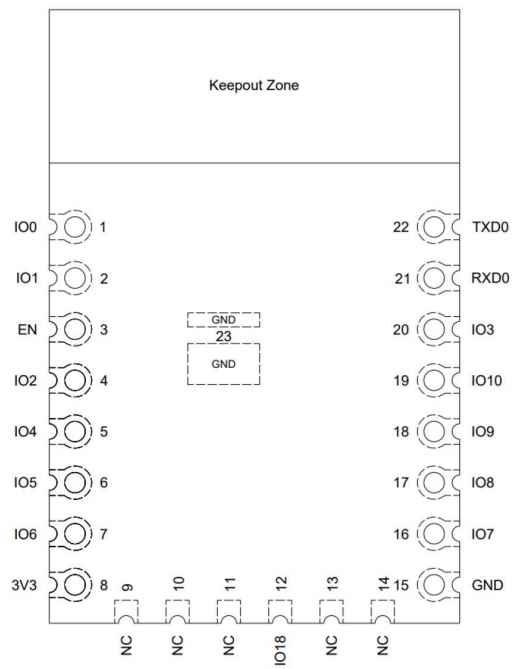
2.2 Pin Descriptions
| Serial No. | Name | Type | Function |
|---|---|---|---|
| 1 | IO0 | I/O/T | GPIO0, ADC1_CH0 |
| 2 | IO1 | I/O/T | GPIO1, ADC1_CH1 |
| 3 | EN | I | High: Disk enable; Low: Disk disable; internal pull-up default. |
| 4 | IO2 | I/O/T | GPIO2, ADC1_CH2, FSPIQ |
| 6 | IO5 | I/O/T | GPIO5, FSPIWP, MTDI, LED PWM |
| 7 | IO6 | I/O/T | GPIO6, FSPICLK, MTCK, LED PWM |
| 8 | 3V3 | P | electricity supply |
| 9 | NC | -- | blank pin |
| 10 | NC | -- | blank pin |
| 11 | NC | -- | blank pin |
| 12 | IO18 | I/O/T | GPIO18 |
| 5 | IO4 | I/O/T | GPIO4, ADC1_CH4, FSPIHD, MTMS, LED PWM |
| 13 | NC | -- | blank pin |
| 14 | NC | -- | blank pin |
| 15 | GND | P | earth (electric connection) |
| 16 | IO7 | I/O/T | GPIO7, FSPID, MTDO, LED PWM |
| 17 | IO8 | I/O/T | GPIO8 |
| 18 | IO9 | I/O/T | GPIO9 |
| 19 | IO10 | I/O/T | GPIO10, FSPICS0, LED PWM |
| 20 | IO3 | I/O/T | GPIO3, ADC1_CH3, LED PWM |
| 21 | RXD0 | I/O/T | GPIO19, U0RXD |
| 22 | TXD0 | I/O/T | GPIO20, U0TXD |
| 23 | GND | P | earth (electric connection) |
3. Module Size and PCB Package Graphics
3.1 Module Size
PCB Size :24±0.3(L)X16±0.3(W)X0.8±0.1(H) 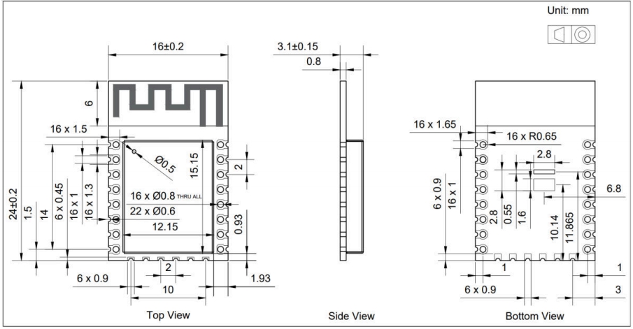
4. Product Packaging Information
Pallet + outer box packaging