NodeMcu-8720DFV1 Development board
NodeMcu-8720DFV1 Development Board Introduction
1 Product Overview
The W5B03A-1720DF development board All modules have accurate graphical graphics so that developers can easily develop and debug the modules. Standard pins on both sides also make operation easier when using the breadboard for development and debugging.it is a multi-radio microcontroller module. The open CPU architecture allows customers to develop advanced applications running on a dual-core 32-bit microcontroller. The radio provides support for Wi-Fi 802.11 a/b/g/n in the 2.4 GHz/5 GHz bands and BLE 5.0 communication.
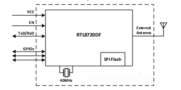
The rich peripherals and high performance make it ideal for smart homes, industrial automation, consumer electronics, etc. The block diagram of the module is shown in Figure 1.
2 External Dimensions
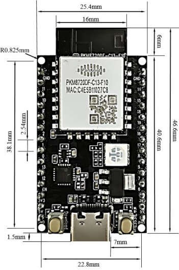
Product Pictures
Product Size
3 Features
- Support 4M flash
- Support 802.11a/b/g/n1x1,2.4 GHz&5 GHz
- Support 20MHz/40MHz bandwidth, MCS7
- Supports Low Power Beacon Listening Mode, Low Power Rx Mode, Low Power Suspension Mode (DLPS)
- Built-in AES/DES/SHA hardware engine
- Supports Arm Trust Zone-M and Secure Boot
- Support SWD debug port access protection and disable mode
- Supports BLE 5.0, central and peripheral modes
- Supports Bluetooth high power mode (up to 10dBm)
- Internal coexistence mechanism Wi-Fi and BT share the same antenna
- Both KM4 and KM0 have a GDMA controller with 6 channels each
4 Application Direction
- Smart Home
- Health and Fitness
- Portable devices
- Medical
- Industrial
5 Main Parameters
| Parameter | Description |
|---|---|
| Module Model Number | NodeMcu-8720DFV1 |
| Package | SMD-22 |
| Dimensions | 24 ± 0.2mm (L) x 16 ± 0.2mm (W) x 2.3 ± 0.1mm (H) |
| Antenna | On-board PCB antenna |
| Wi-Fi Frequency Range | 2412MHz ~ 2484MHz (2.4GHz ISM Band), 5180MHz ~ 5825MHz (5GHz) |
| Bluetooth | BLE 5.0 |
| Bluetooth | BLE 5.0 |
| Bluetooth | BLE 5.0 |
| Storage | -40°C to 125°C, < 90% RH |
| Power Supply Range | (3.3 ± 10%)V, current > 450mA |
| Interface | UART/GPIO/ADC/PWM/I2C/SPI/SWD/USB 2.0 HS/SDIO/DMIC/IR/I2S |
| Module Approvals | FCC/CE/SRRC |
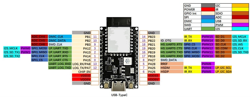
6 Pin Definitions
| No. | Pin name | Description |
|---|---|---|
| 0 | PA15 | LP_UART_CTS/SPI1_CS |
| 1 | PA14 | LP_UART_RTS/SPI1_CLK/I2S_SD_TX2 |
| 2 | PA13 | LP_UART_RXD/SPI1MISO/PWM1/I2S_SD_TX1 |
| 3 | PA12 | LP_UART_TXD/SPI1_MOSI/PWM0/I2S_MCLK |
| 4 | - | - |
| 5 | PA28 | RREF/PWM6 |
| 6 | PA26 | HSDP/LP_I2C_SDA/PWM5/IR_RX |
| 7 | PA25 | HSDM/LP_I2C_SCL/PWM4/IR_TX |
| 8 | PA27 | SWD_DATA |
| 9 | PB3 | SWD_CLK/ADC_CH6 |
| 10 | PB2 | DMIC_DATA/ADC_CH5 |
| 11 | PB1 | DMIC_CLK/ADC_CH4 |
| 12 | LOG_TX/PA7 | UART_LOG_TXD |
| 13 | LOG_RX/PA8 | UART_LOG_RXD |
| 14 | PB23 | IR_TX/PWM15/SD_D1/I2S_MCLK |
| 15 | PB22 | ID_OTG/IR_RX/ PWM14/S_D0/I2S_SD_RX |
| 16 | PB19 | HS_UART0_TXD/SPI0_MISO/PWM11/SD_D3/I2S_SD_TX0 |
| 17 | PB18 | HS_UART0_RXD/SPI0_MOSI/PWM10/SD_D2 |
| 18 | PB21 | HS_UART0_RTS/SPI0_CS/PWM13/SD_CLK/I2S_WS |
| 19 | PB20 | HS_UART0_CTS/SPI0_CLK/PWM12/SD_CDM/I2S_CLK |

.png)


