Introduction to Tasmota
Prerequisites
1 Required hardware
1.1 ESP devices
Every device based on the espressif ESP8266, ESP8285, ESP32, ESP32-S, or ESP32-C3 chipset can be flashed using Tasmota. The term ESP refers to any of them.
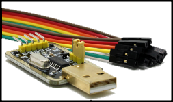
1.2 Serial Programmer
The power supplied to the deviceis one of the most important factors for flashing and stable operation of the device. You must ensure that the device is getting enough power (current and proper voltage tage levels) to properly refresh the firmware on the device.
-
CH340G is recommended as the most reliable and cheapest starter (CH340G, Sparkfun、solder connection、CH340N with AMS1117)。
-
Featured VoltLink - USB to Serial Adapter Board based on the popular CP2102N chip, with built-in ESP auto-reset circuit and 500mA regulator!
-
CP2102 or PL2303 - Suitable for some devices, but may require the use of an external 3.3V power supply. Not recommended for beginners!
-
NodeMCU If you disable the on-board ESP by bridging GND to the RST or EN pins, and connect TX and RX directly to another ESP82xx instead of cross-connecting them, you can also use the NodeMCU (or similar device) as a reliable You can also use the NodeMCU (or similar device) as a reliable serial programmer.
**Note:**
Some adapters can switch the data pins between 3.3V and 5V but still provide 5V on the power pins, which will irreparably damage your device. You must make sure that the data (RX and TX) and VCC pins are set to 3.3V.
Many serial programmers do not have an on-board voltage regulator like the one shown. the ESP requires a minimum of 150mA, and many 3.3V serial programmers are unable to supply this much current, as many serial programming tasks do not require a lot of power.
When using an external 3.3V power supply, make sure that the ground (GND) of the two are connected together, which ensures a common ground. the PC power supply can be used as a power source for the 3.3V DC power supply.
Devices with a USB upload port usually have a serial programmer built in,for example NodeMCU、D1 mini 或 M5Stack Products。 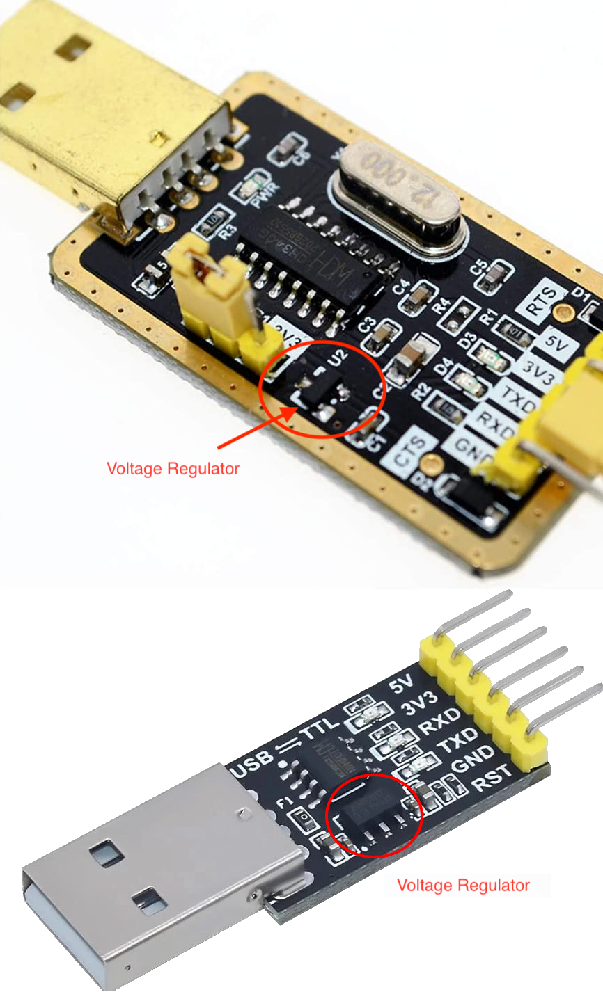
1.3 Soldering tools
To solder, you will of course need a soldering iron, tin and some flux. If you are not familiar with soldering, check out some soldering tutorial videos.
If you are intimidated by soldering, there are 3D printing jigs available for different modules and devices. In the worst case scenario, you can use jumper wires to hold the joints in the pinholes tightly in place during flashing, but it's not a foolproof process and flashing can fail.
1.4 Jumper cables
You can use any type of wire, but jumper cables (also known as Dupont wire) are more practical than soldering and desoldering.
1.5 Pinouts
Poke pins are available in either male or female versions. Choose according to your jumper connector.
1.6 Computer with Linux, Windows or MacOS
You need a computer with a USB port to upload firmware to your device and configure it.
1.7 Smartphone
Tasmota installed from pre-compiled binaries needs to be configured to work with your Wi-Fi network before you can access the Tasmota Web UI.This is typically done by using a smartphone (or tablet or computer with Wi-Fi) connected to a Tasmota Wi-Fi Access Point.
2 Required software
2.1 Tasmota Firmware Binaries
Download the Tasmota firmware binaries (.bin). If you are not sure which binary is right for you, simply start with the build sheet or consult the build sheet to see which features you need. tasmota.bin
The official version of the binaries can be downloaded from the firmware server.
The latest development branch binaries are only available from our OTA server. The latest merged development code is compiled hourly.
2.2 Flashing Tools
- Tasmota Web Installer - Flashes Tasmota for ESP82XX and ESP32 using Chrome-based browser
- Tasmotizer - Flashing and firmware download tool for ESP82XX only. (Windows, Linux or Mac)
- ESP-Flasher - GUI flasher for Tasmota based on ESP82XX and ESP32 esptool.py. (Windows, Linux or Mac)
- Esptool.py - Loxin's official flasher for the ESP82XX and ESP32.
Compile Tool (optional)
If you want to modify the code or default settings and compile your own Tasmota firmware.
3 MQTT Knowledge
Tasmota is intended to be controlled and communicated via MQTT. To use it to its full potential, you need an MQTT proxy.
Read TASMOTA's article on MQTT to see why it is critical in Tasmota.
4 Hardware preparation
We need to connect to the serial programming interface of the ESP chip. This is done by connecting our serial to USB converter TX and RX pins to the ESP RX and TX pins and powering the chip using the 3.3V and GND pins.
In most cases, these pins are provided as pin holes or pads on the PCB, but pin connectors or jumpers need to be soldered or otherwise applied. In some cases you will need to solder the wires directly to the chip's pins, which requires some experience and good soldering equipment.
⚠️Do not try to flash your device while it is connected to the mains ⚠️
⚠️If you don't know what you're doing, you could get electrocuted ⚠️
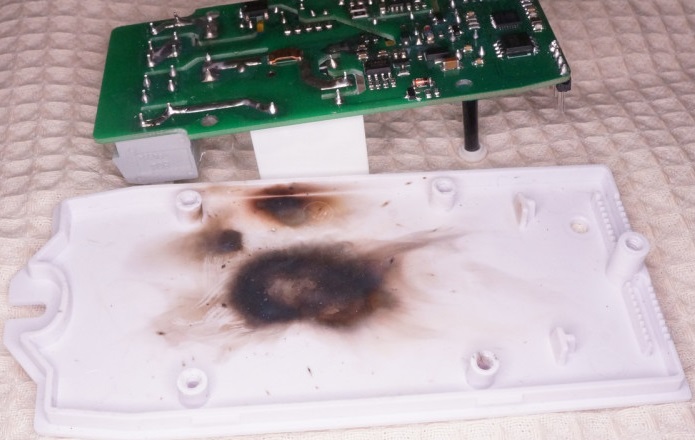 If you're not careful, your own health is at risk. Shorting out the serial interface using power AC power can burn out your device and the serial adapter, and can also damage or break your computer. When working through a serial connection, or even when opening the device case It is important to always disconnect all power cords from the device.
4.1 Serial connection
The pins are labelled differently for each device. If the labels are not visible on the PCB, refer to the device blinking guide or search the Internet for the correct pin locations. Device-specific instructions and restrictions are documented in the Tasmota Supported Devices repository. Pinouts for commonly used Wi-Fi modules can be found here
After identifying the pins on the device, connect the wires according to the table:
| Serial Adapter | devices |
|---|---|
| 3V3 | 3V3 or VCC |
| RX | TX |
| TX | RX |
| GND | GND |
Please note that TX from the adapter goes to RX on the ESP device and RX from the adapter goes to TX on the device! 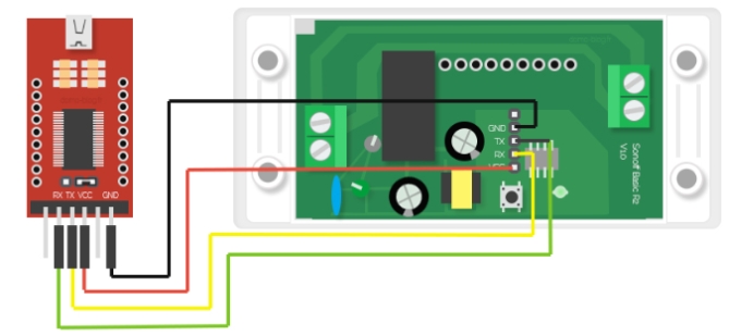
4.2 Programming Mode
Typical GPIO0 Location
The ESP needs to enter Programming Mode or Flash Mode before it can upload firmware. This is done by connecting the GPIO0 pin to GND when the chip boots.
On many devices, the installed controls are connected to GPIO0 and GND to ease entry into programming mode. In other cases, you will need to bridge the pins on the PCB or directly to the chip with jumpers. The GPIO0 location for popular modules can be found in Pin Arrangement! Device specific instructions are documented in Tasmota Supported Device Repository. 
To place the ESP in programming mode: 1. Disconnect the serial programmer and power supply 2. Bridge GPIO0 and GND (either by pressing an on-board button or by connecting to a wire) 3. Connect the Serial Programmer to your computer. 4. After a few seconds, disconnect GPIO0 from GND (by releasing the button or disconnecting the wire connection). On devices that do not provide a GPIO0 connection button, it may be easier to leave the wired bridge in place throughout the blinking process (erase and upload). Doing so will not create any problems. After the firmware has been successfully uploaded, remove the bridge. This allows the device to boot up normally.
esptool.py Programming Mode Test
You can test if your device is in programming mode by trying to read from the ESP82xx chip. This requires . Instructions for installation and use are provided below. For example (this will be your COM port): esptool.yesptoolCOM5
esptool.py -p COM5 read_mac(It should read the MAC address. It may then fail during the upload and run of the "stub". This is normal.
esptool.py -p COM5 flash_id
If all went well, you are now in programming mode and ready to continue flashing. If the refresh process does not start, disconnect the device and retry these steps.
4.3 Common Errors
- Cable connections and solder joints - Double check all connections and check for solder overflow.
- Using a USB cable - Some USB cables are for charging only and do not connect the cable needed to load firmware to the device.
- The serial programmer is not providing enough power. This can result in failed flashing or complete corruption of the flash memory. Use a separate 3.3V power supply to provide more power, or use an adapter with a better power supply. Make sure you use the same GND wire for all DC voltages.
- Recheck your serial programmer to make sure it is supplying 3.3V and not 5V. 5V can damage the ESP chip!
- Release the GPIO0 button/wire before booting is complete - It is safe to connect GPIO0 to GND throughout the programming process (erase and upload). Just be sure to remove the GPIO0 to GND bridge before booting the device for normal operation.
- Make sure that the RX pin is connected to the TX pin between the serial adapter and the ESP device and vice versa. Note: Some devices may mark the TX and RX pins as opposite. In this case, connect the TX of the adapter to the TX and the RX to the RX pin.
- Before uploading the Tasmota firmware binaries, erase the flash memory and reboot the power supply. Failure to erase may leave residues of previous flash contents, which may interfere with new firmware operation.
5 fix
If you have followed Hardware Preparation, your device should be in Programming Mode and ready to install the Tasmota firmware binaries. To install: you will go to the original Tasmota web page
6 After configuration
Devices running Tasmota can now be controlled.
See all the features of Tasmota and ways to integrate it with other platforms.
⚠️ warning
If you experience power fluctuations in the grid, it is best to immediately disable the power cycle recovery feature immediately using the command SetOption65 1, otherwise you may end up with firmware defaults on your device.